The Story of the
Holton Heath, Dorset, UK

History & Manufacture of Nitroglycerine
History
Nitroglycerine was first produced by Ascanio Sobrero, Professor of Chemistry at the University of Turin in 1847. He reported “when glycerol (glycerine) was poured into a mixture of sulphuric acid and nitric acid which had been cooled an oily liquid is formed.” No significant use was made of the substance until 1863 when Alfred Nobel began making it on a large scale at a factory in Stockholm. Unfortunately several serious accidents took place including one which killed his younger brother, and it was not widely used, indeed, in some countries even its manufacture was banned. A major problem was found to be residual acid from the nitrating process leading to decomposition and explosion.
In 1866 Nobel demonstrated that by absorbing the nitroglycerine onto kieselgur to produce Dynamite he had a powerful explosive for blasting. Further developments in manufacturing technique, ensuring the elimination of residual acid by careful washing led to the production becoming safer.
Manufacture
Initially nitroglycerine was made by a batch process, at first in quite small batches but by the time RNCF was in operation the batch size had risen to 1.5 tonnes. This was manufactured by introducing 3700kg. of a mixture of 55% sulphuric acid and 45% nitric acid into a Nathan-Thomson-Rintoul nitrator. The sulphuric acid does not form part of the reaction but mops up the water which is formed by the nitration process and would otherwise dilute the nitric acid and limit the amount of nitroglycerine produced from the glycerine charge.
The device was developed by Lt. Col. Sir F. L. Nathan, J.M. Thomson and W. Rintoul at the Royal Gunpowder Factory, Waltham Abbey. The nitrator-separator which they produced is shown in Schematic 1 (right) and consisted of a cylindrical lead vessel (a) with the bottom sloping in one direction and containing lead cooling coils, using ammonia as a coolant (h) and air pipes (g) for agitation. The vessel was fitted with a conical cover and inspection windows. A thermometer was also fitted through the cover. The pipe (k) left one side of the cylinder after which it divided, the vertical portion (m) provided a means of fume
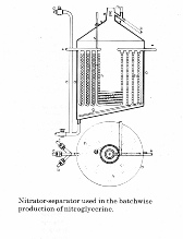
removal whilst the sloping pipe (k) opened into an inclined gutter leading directly to the pre-wash tank. Acid was introduced through the pipe (d) into the lowest point of the nitrator so as to avoid nitroglycerine getting into the acid lines. There were two additional branches to this pipe one leading to the waste acid “egg” and the second to the drowning tank used for safety purposes if the reaction became uncontrolled.
A 670kg. charge of glycerine was steadily added to the acid in the form of a spray. The rate was controlled so as to limit the temperature of the reaction. The preferred temperature was about 10C but could be higher, but anything over 20C was approaching a runaway reaction. In the event of this happening the whole charge could be dumped into a large tank of water known as the “drowning tank”. In 40 years of operations at RNCF this was never necessary. The reaction of the whole of the glycerine took about an hour after which the nitroglycerine which forms on the surface of the acid was run off into the pre-wash tank by injecting additional acid into the bottom of the nitrator. The nitroglycerine was then put through additional washes with water and a dilute solution of washing soda. The final part of the process was to pass the nitroglycerine through a sponge filter.
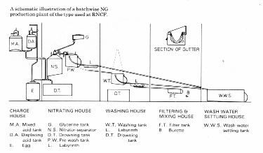
Schematic 2 (left) shows the arrangement of two nitrator-seperators and the pre wash tank. A photograph of the plant with its operators is shown in the gallery. Schematic 3 (below) shows the complete plant with washing and filtering sections. There were two separate nitration facilities, which differed slightly in that the diagram shows the process in the case of the AB1 house where the washing was done in a separate house whilst in the ABC house the final washing was carried out in the same building.
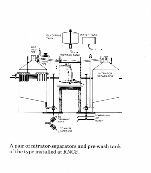
Schematic 2
Schematic 3 >
Please mouse over graphics to enlarge
The nitrators and washing equipments were contained in lightweight wooden buildings so that, in the event of an explosion damage from flying debris would be minimised, and these buildings were within earthen embankments. To eliminate any likelihood of sparks occurring no electrical power was allowed in the buildings and ferrous materials were avoided in construction of equipment. Lighting was by way of exterior lamps shining through windows. The whole nitroglycerine plant was built on a slight hill so that transfer of the material from one process to another could take place by way of lead lined gutters using gravity to drive the flow.
After passing through the washing and filtering processes the nitroglycerine was carefully transferred to special hand trucks which ran on rubber tyred wheels on a concrete railway.
The first batch of nitroglycerine from the ABC plant was produced on 12th October 1916 and the last on 18th September 1945. The date of the first batch from the AB plant is not known but probably not very different. The last batch was produced on 23rd June 1931 just prior to the major explosion which destroyed the nitrator and its associated washing plant.
Later in the 1930s attention was given to replacing the AB plant and it was decided to install a continuous production unit rather that the original batch plant. This was based on the Schmidt process and the equipment was acquired from Germany and installed by German engineers. In essence the process was similar with acid being injected into a nitration vessel and glycerine injected into the top in the acid to glycerine ratio of 5.5 to 1. Again coolant was circulated to keep the reaction temperature down to an acceptable level. The nitroglycerine then went through several more washing stages with water and a dilute solution of washing soda. This continuous process was capable of producing some 6ookg. of nitroglycerine per hour.
The photographs in the gallery below show the buildings and equipment including the associated coolant plant and air compressors.
By Dr Bob Dukes